How to export a plane to BF2-BF2142
Tutorial by [XWW2]mschoeldgen on Battlefield Singleplayer Forums. Done on 3DS Max 9, but can be done on versions 6-9. Requires BF2 Editor + BF2 3DS Max 6-9 Plugin.
Posted by ytres on Nov 14th, 2010 - Advanced Client Side Coding
Making a plane for BF2/BF2142 by [XWW2]mschoeldgen
Note that i had to split up the tutorial into more than one post to workaround the maximum picture-per-post limit. Part 1:
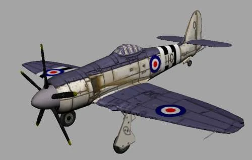
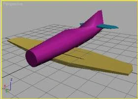
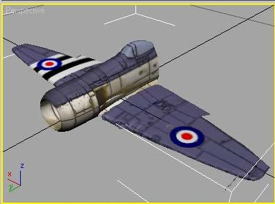
In this tutorial i'd like to describe the way of converting a common plane model into a flyable PCO for Battlefield. I will cover the hierarchy, material setup and plane specific coding . As a base i used the model of a 'Hawker Seafury' found on 3dkingdom.org The model was made by Muzzmah and he supplied textures for the plane although they where on several different sheets. For BF puposes its better to have them on a single texture sheet, so i assembled them onto a single sheet and re-uvmapped the plane elements onto this sheet.
 |
|---|
Image File: planeA.jpg
UVMapping
is covered elsewhere. Lets focus on the plane here. I assume you have a
textured plane (or whatever)and want to know how to make a BF model out
of it.
Things you need :
- 3DSMax6 - 3DSMax9 and the appropriate BF2 export tools for your version of Max. If you're smart
you can probably make the model work in gmax. I have included the *.3DS file in the download so that you can import it into gmax.
- the BF2Editor and a mod where you can safely include the new model.
- about 1 to 12 hours of time - dependent on your grasp of Max tongue.gif
- a readymade 3D model of your vehicle.
I decided to make a plane because they have wheels and wings so that i can cover the wheel modelling as well. A boat is much more easy, btw. The included download ( in Post #5 ) contains a model for Max7 - bad for Max 6 users but good for anyone else. There's also the readily exported and coded plane in that download.
i cannot stress the existence of a good texteditor enough - you should grab one with syntax highlighting adjustable to the BF syntax. This comes in very handy. Personally i use 'SourceEdit' with a 'BF2' language extension. It has its flaws and you might want to look into 'Programmers Notepad' or 'Notepad++'
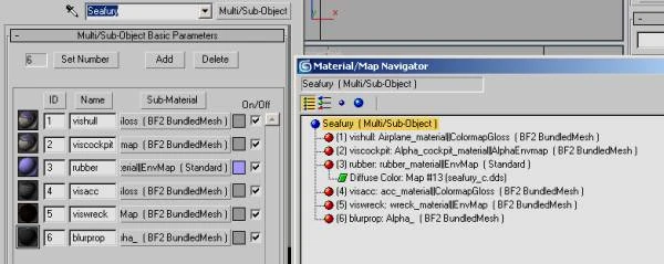
Material Setup We will need at least 5 materials for the plane: hull, cockpit glass, rubber, the wreck material and the blurred propeller texture. Create a 'Multi/Sub' Material in the Material Manager and create appropriate Submaterials: Material ID 1 will be the basic material for hull and wings, Material ID 2 carries the alpha'd cockpit glass and Material ID 3 is the rubber:
 |
|---|
Image File: planeC.jpg
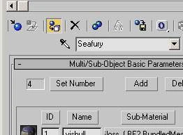
The material names are important: 'Airplane_material||ColormapGloss' for the body, 'Alpha_cockpit_material||AlphaEnvmap' for the cockpit glass and 'rubber_material||EnvMap' for the wheels. The blurred Propeller texture will need 'Alpha' and the wreck texture gets a 'wreck_material||EnvMap' name. A small excurse: The Seafury has a wingspan of rougly 11 meters and a length of just above 10 meters. For texturing the model i thus selected a texture size of 1024 * 1024. A few parts didn't fit on the main texture , like the cockpit instrument panel, the prop texture and some metal parts from the Landing Gears. I therefore added a 4th texture slot (again a BF2BundledMesh) and put my additional texture in there. Now select all parts of the model and press the 'Assign material to Selection' button, which is yellow in this screen
 |
|---|
Image File: planeD.jpg
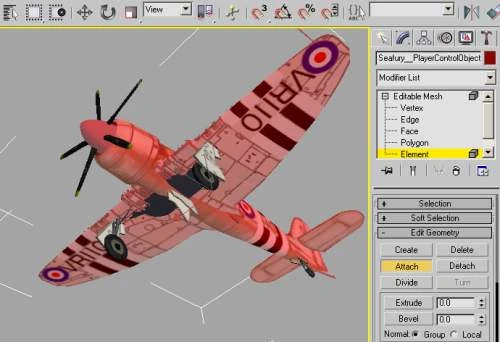
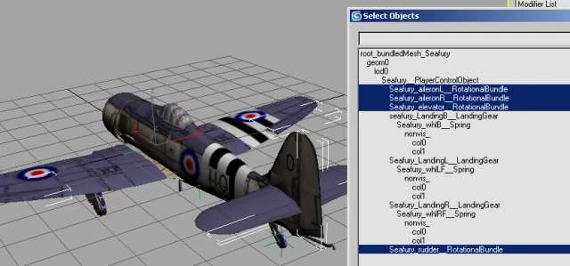
Now select a single element of the fuselage and name that 'Seafury__PlayerControlObject'. Keep the Mesh selected and by pressing 'Attach List' in the Mesh rollout (its under 'Edit geometry') open the 'Select by Name' window. Select all pieces you think will belong to the main mesh. For the Seafury this includes all wings, the complete hull except the landing gears and wheels. 'Pressing 'Attach' in the Select window puts all these meshes into a single one.
 |
|---|
Image File: planeB.jpg
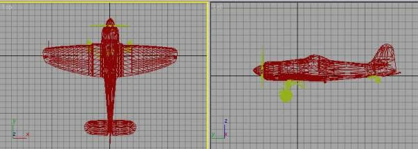
A quick word about scaling: BF2/2142 use a metric system so when your sytem setup is set to 'Metric' you should be fine. Choose a unit of 0.1 m. When working in Generic Units the scale from 3DS to BF2 is 10:1. Orientation of the model should be 'Nose Up' in the Top View and the Origin ( 0/0/0 )of the model should be in the Center of Gravity.
 |
|---|
Image File: planeG.jpg
Part 2:
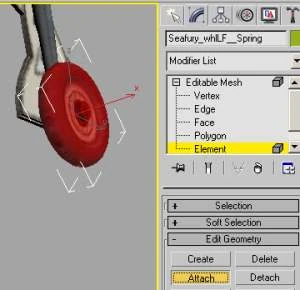
Creating the hierarchy: Battlefield 2/2142 needs a certain structure of the model where each part is in a tree of objects. Some of these objects are only helpers (dummies) and some of the parts are real meshes. Planes will need at least some wheels to land on and for take-off. Lets create our first wheel by selecting the torus of the left wheel and attaching the hub and the axle to it:
 |
|---|
Image File: planeE.jpg
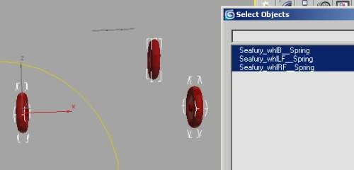
Give this object a name like 'Seafury_whlLF__Spring' where the most important part is '__Spring'(double underscore !), telling BF to give this part wheel physics. I prefer to use unique names to aviod conflict with other objects in the mod so i chose a 'Seafury_' prefix for all my parts. Repeat this for the right wheel and (if your model has it) the back wheel, each now having a unique name:
 |
|---|
Image File: planeF.jpg
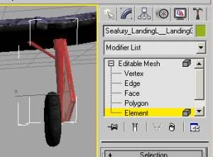
The Seafury has all 3 wheels retractable. BF2 has a custom RotationalBundle for this purpose, the so-called LandingGear. Lets now select the parts for it and attach them into a single Mesh, giving it a useful name in the process 'Seafury_LandingL__LandingGear' :
 |
|---|
Image File: planeH.jpg
Repeat this for the suspension of all wheels (3 in this case). When finished, you end up with something similar to this:
 |
|---|
Image File: planeI.jpg
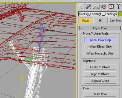
LandingGears
will rotate around their pivots, so its important to move them into a
good position. Do this by selecting your landing gear mesh and opening
the 'Hierarchy' Tab. Press 'Affect Pivot Only' and move the pivot to the
rotation center:
 |
|---|
Image File: planeJ.jpg
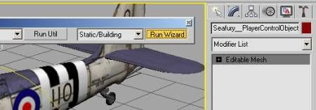
Repeat this for the two remaining wheels and also make sure that all pivots are 'Aligned to World' by pressing the corresponding button. It cannot hurt to check all your meshes for this alignment now. It is also a good idea to press 'Reset Transform' and 'Reset Scale' while you have the pivot selected, its necessary to have a clean model for the game to accept it (which is true for most games, not only the BF series) O.k., our plane is in a state were we can think about creating the hierarchy. For this purpose we 'misuse' the Static wizard in the BF2 tools for 3DS Max. Thanks to Rexman, this provides a basic hierarchy with root and basic geometry helpers. Note that the newer toolsets look a bit different and the Wizard is fired through a button. The latest PoE2 tools also provide a 'Bundledmesh' wizard, but its not really a necessity to use it here. Select your main mesh (Seafury__PlayerControlObject) and open the BF2 Utilities. Select 'StaticWizard' and then press 'Run Wizard':
 |
|---|
Image File: planeK.jpg
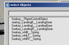
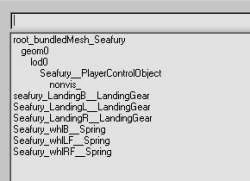
We now have some new objects in the scene,some of them will need renaming:
 |
|---|
Image File: planeL.jpg
The root is a point helper and needs renaming to 'root_bundledMesh_seafury'. The anchor is a dummy which we can use later on for tagging the collisionmeshes,lets rename it to 'nonvis_':
 |
|---|
Image File: planeM.jpg
Now we need to make the landing gears children of the main body and the wheels children of their landing gear. For this purpose , Max provides the 'SelectandLink' button in the top Toolbar:
 |
|---|
Image File: selectandlink.jpg
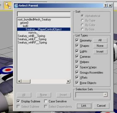
Start by selecting all three landing gears and press the 'Select and Link' button. When you now select the main mesh, it will become the parent to these objects. I find it easier to use the select by name window for this:
 |
|---|
Image File: planeN.jpg
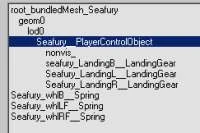
Finish the parenting process by pressing the 'Link' button in the lower right of this window. When you go back to normal selection mode and reopen the window , it will look like this:
 |
|---|
Image File: planeO.jpg
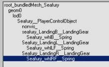
The wheels need to be children of the resp. landing gear, so select each wheel and parent it to its Landing gear:
 |
|---|
Image File: planeP.jpg
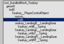
This post has been edited by mschoeldgen: Sep 19 2009, 08:40 AM Part 3: We will now create some basic collisionmeshes. We need three of them for the main body and two each for the wheels. The most detailed collisionmesh should be the one for projectiles , called 'col0'. 'col1' is for collision with other objects and the ground, while 'col2' is used for soldier collisions. Lets create the col0 by cloning the main body. To do this, select your main mesh and choose 'Clone' from the 'Edit' menu in Max. Make it a 'Copy' and rename the clone to 'col0' (without the quotes) and parent it to the 'nonvis_' dummy:
 |
|---|
Image File: planeQ.jpg
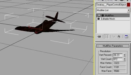
We have relatively high polycount on the col0, lets reduce it by applying a 'MultiRes' modifier to this mesh. Select the col0 mesh and choose 'MultiRes' from the Modifier pop-up menu. Press 'Generate' in the multires rollout and decrease vertex count. As an aid, you could hide the other parts of the plane for this, making it easier to judge between accuracy of the mesh and polycount. For the Seafury, it shows we can safely reduce the polycount to 20% of the original model without damage to the outline. This greatly reduces collision calculations done by the server later on and will free up resources for other stuff. To have a sane uvmap now that we have deleted tons of vertices, add an 'Unwrap UVW' modifier with channel 1 selected and collapse it on the col0 mesh. This gets rid of all the dead vertices. The col1 and col2 meshes can be made with simple boxes and cylinders. For the Seafury, 2 boxes and a deformed cylinder cover the model quite good:
 |
|---|
Image File: planeR.jpg
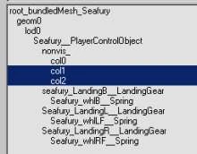
The important part for the col1 and col2 is to not extend the col0 mesh , that is the col0 mesh should enclose col1 and col2 to give the correct collision behaviour. Attach the boxes and cylinder to a single mesh after converting them to 'Editable Mesh', give it the 'col1' name and don't forget to apply our material setup to the new col1 mesh by pressing 'Assign material to selection' in the Material Manager. Parent it to the 'nonvis_' dummy and clone it to a copy named 'col2' (still leave out the quotes )
 |
|---|
Image File: planeS.jpg
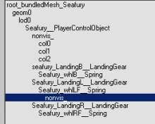
We will now create the collisionmeshes for the wheels. Wheels need a col0 which is a cylinder and a col1 which consist of a single face pointing to the ground, located on the lower edge of the wheel. To start, select the existing 'nonvis_' dummy, clone a copy from it and parent the clone to a wheel :
 |
|---|
Image File: planeT.jpg
Move the helper to the center of the wheel. Now create a cylinder with roughly the size of the wheel and parent it to this 'nonvis_' helper. It only needs to have 8-10 sides (staying low-poly)and a single height segment. Again, apply our material setup to this mesh. Now go to bottom view and create a 'plane' with 1 height and 1 length segment, located just below the wheel.Parent it to the 'nonvis_' of the wheel, too. Convert both objects to editable meshes and delete one face from the col1:
 |
|---|
Image File: planeU.jpg
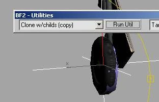
Remember that Material ID 3 is our rubber material, we should apply this ID to the wheels' collision meshes. Do this by selecting the col0 mesh, go to 'Element' selection and find 'Surface Properties' in the Element rollout. Press 'Ctrl-A' to select all elements (should only be one) and set the material ID to 3. Repeat this for the col1 mesh. O.k., collision setup for the left wheel is complete. Instead of going through the same process for the right wheel, we use another utility provided in the BF2 tools for 3DS, the 'Clone with children (Copy)' helper script. Select the 'nonvis_' helper from the left wheel and once again open the BF2 Utilities. You will find the function on the left side of the utilities.
 |
|---|
Image File: planeV.jpg
Press 'Run Util', and parent the new 'nonvis_' (with its children) to the right wheel. Now move this nonvis_ dummy to the right wheel and notice the child meshes following it. Center it on the right wheel and once again run the 'Clone with children (copy)' Utility, this time for the back wheel. Move the new nonvis_ helper to the center of the back wheel.
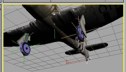
The back wheel is smaller than the front wheels. When we rescale the helper 'nonvis_', we can simultanously rescale its children. We only need to reset transform and scale on the helper and children after this. We should now have all wheels equipped with collisionmeshes:
 |
|---|
Image File: planeW.jpg
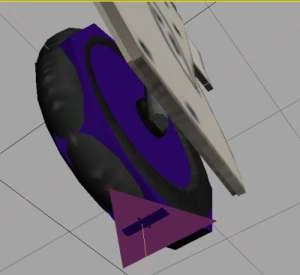
Except for the 1P- and the wreck model, the plane would be ready to fly, but we want some more eyecandy on it in the form of moveable control surfaces. We can now detach some elemnts from the hull to make ailerons, elevator and the rudder. The left aileron is created by selecting all faces making it up and detach them to a new mesh - 'Seafury_aileronL__RotationalBundle'. RotationalBundles do not contribute to plane physics but can be controlled through the standard controls, like PIYaw, PIPitch and PIRoll.Select the hull mesh and then go to 'Face' Selection. Collect the faces making the aileron then Press 'Detach' in the Face rollout.
 |
|---|
Image File: planeX.jpg
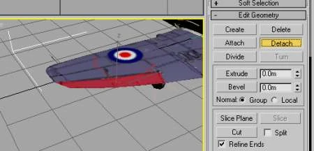
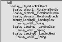
Repeat the process to create a 'Seafury_aileronR__RotationalBundle', the 'Seafury_elevator__RotationalBundle' and the 'Seafury_rudder__RotationalBundle'. They all will be parented to the main hull of the airplane.
 |
|---|
Image File: planeY.jpg
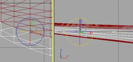
Again, these meshes will rotate around their pivot, so we need to carefully adjust them to be in the center and axis of rotation. Select the left aileron, open the hierarchy tab and 'Affect Pivot Only'. Move the pivot to the front edge of the aileron and center it on the middle between upper and lower side of the wing. Rotate it carefully to align it with the front edge and the axis of the aileron:
 |
|---|
Image File: planeZ.jpg
You should now repeat this pivot adjustment for all other control surfaces.
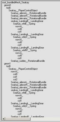
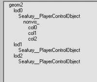
O.k. what we need to add to the model is both the 1P model which will be visible to the Player after entering the plane and the wreck model shown after destruction. Once again, Rexman's 'Clone with childs(Copy' utility comes in handy biggrin.gif. Select the geom0 dummy and open the BF2 utilities. Select the clone function and press 'Run Util'. Leaver the utility open and rename the created dummy to 'geom1'. Again press the 'Run Util' button and this time rename the new dummy to 'geom2'. You should end up with a much longer hierarchy now:
 |
|---|
Image File: planeAA.jpg
Its so long it will not fit on a screen anymore, but we can erase quite a few objects from it now. The geom0 model will not need any collisionmeshes. The wheels are not visible and neither elevator nor rudder will be on screen so we can safely delete them from geom0:
 |
|---|
Image File: planeAB.jpg
That looks better. The wreck will need collsionmeshes, but we can reattach the control surfaces to the main mesh and erase the landing gears with the wheels:
 |
|---|
Image File: planeAC.jpg
Apply the 'wreck_material' to the hull mesh and the collisionmeshes of the wreck (geom2). An easy way to set the faces of several meshes at once is to select them all and add an 'Edit Mesh' modifier on top of them. In this modifier select 'Face' mode , press 'Ctrl-A' to select all faces and set the ID to 5 in the face rollout. When finished, collapse the 'Edit Mesh' modifier.
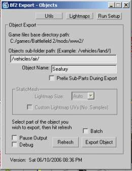
This post has been edited by mschoeldgen: Sep 19 2009, 07:57 AM Part 4: We are finally ready to try a first export to the game format now ! Open the BF2 exporter and fill in the destination path inside the Objects folder, for our plane '/vehicles/air/' seems to be a good place. As a smart person, i already created a /Seafury folder inside it and prepared my textures folder in it in advance.
 |
|---|
Image File: planeAD.jpg
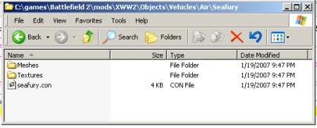
We don't need to check the 'prefix parts' box for we did that ourselves but just press 'Export Object'. If everything went well, we now have a /meshes folder and a Seafury.con file in the destination folder 'Seafury'
 |
|---|
Image File: planeAE.jpg
Lets open the .con file and look for any undefined materials and for a healty structure. The con file represents the hierachy in text, so a child X of an object Y should be an added template to Object Y. In our plane everything looks good ans we don't have any wildy rotated objects,
which would point to non-aligned pivots.
GeometryTemplate.create BundledMesh seafury
CollisionManager.createTemplate seafury
ObjectTemplate.create PlayerControlObject seafury
ObjectTemplate.saveInSeparateFile 1
ObjectTemplate.creator XWW2:mscho
ObjectTemplate.collisionMesh seafury
ObjectTemplate.mapMaterial 0 Airplane_material 0
ObjectTemplate.mapMaterial 1 wreck_material 0
ObjectTemplate.mapMaterial 2 rubber_material 0
ObjectTemplate.hasCollisionPhysics 1
ObjectTemplate.physicsType 3
ObjectTemplate.hasMobilePhysics 1
ObjectTemplate.geometry seafury
ObjectTemplate.addTemplate Seafury_aileronL
ObjectTemplate.setPosition -4.2701/-0.0012/-0.6363
ObjectTemplate.addTemplate Seafury_aileronR
ObjectTemplate.setPosition 4.2971/0.0335/-0.6367
ObjectTemplate.addTemplate Seafury_elevator
ObjectTemplate.setPosition 0.0175/0.7641/-6.2759
ObjectTemplate.addTemplate seafury_LandingB
ObjectTemplate.setPosition -0.0486/-0.0407/-5.3449
ObjectTemplate.addTemplate Seafury_LandingL
ObjectTemplate.setPosition -1.8118/-0.2245/0.3093
ObjectTemplate.addTemplate Seafury_LandingR
ObjectTemplate.setPosition 1.7208/-0.1919/0.3064
ObjectTemplate.addTemplate Seafury_rudder
ObjectTemplate.setPosition 0.0108/1.1534/-6.3506
ObjectTemplate.create RotationalBundle Seafury_aileronL
ObjectTemplate.hasMobilePhysics 1
ObjectTemplate.geometryPart 1
ObjectTemplate.create RotationalBundle Seafury_aileronR
ObjectTemplate.hasMobilePhysics 1
ObjectTemplate.geometryPart 2
ObjectTemplate.create RotationalBundle Seafury_elevator
ObjectTemplate.hasMobilePhysics 1
ObjectTemplate.geometryPart 3
ObjectTemplate.create LandingGear seafury_LandingB
ObjectTemplate.hasMobilePhysics 1
ObjectTemplate.geometryPart 4
ObjectTemplate.addTemplate Seafury_whlB
ObjectTemplate.setPosition -0.0065/-0.3008/-0.3894
ObjectTemplate.create Spring Seafury_whlB
ObjectTemplate.collisionPart 5
ObjectTemplate.hasCollisionPhysics 1
ObjectTemplate.physicsType 3
ObjectTemplate.hasMobilePhysics 1
ObjectTemplate.geometryPart 5
ObjectTemplate.create LandingGear Seafury_LandingL
ObjectTemplate.hasMobilePhysics 1
ObjectTemplate.geometryPart 6
ObjectTemplate.addTemplate Seafury_whlLF
ObjectTemplate.setPosition 0.1608/-1.2177/0.2213
ObjectTemplate.create Spring Seafury_whlLF
ObjectTemplate.collisionPart 7
ObjectTemplate.hasCollisionPhysics 1
ObjectTemplate.physicsType 3
ObjectTemplate.hasMobilePhysics 1
ObjectTemplate.geometryPart 7
ObjectTemplate.create LandingGear Seafury_LandingR
ObjectTemplate.hasMobilePhysics 1
ObjectTemplate.geometryPart 8
ObjectTemplate.addTemplate Seafury_whlRF
ObjectTemplate.setPosition -0.1576/-1.2389/0.2216
ObjectTemplate.create Spring Seafury_whlRF
ObjectTemplate.collisionPart 9
ObjectTemplate.hasCollisionPhysics 1
ObjectTemplate.physicsType 3
ObjectTemplate.hasMobilePhysics 1
ObjectTemplate.geometryPart 9
ObjectTemplate.create RotationalBundle Seafury_rudder
ObjectTemplate.hasMobilePhysics 1
ObjectTemplate.geometryPart 10
include seafury.tweak
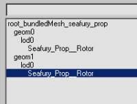
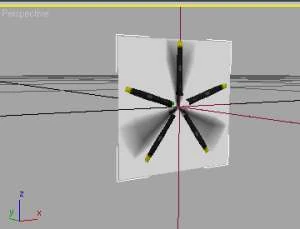
Before we come to the coding part, lets first think about a vital part for any prop-driven plane - the Propeller biggrin.gif The Propeller is made of a '__Rotor' Object with 2 geoms. The geom0 is the solid model which can be seen on a stopped or slow rotating engine and the geom1 is a texture carrying the blurred propeller image. We already have the material for the solid model but the material for the blurred texture has to be added. Add a new material to the material setup and call it 'Alpha'. The propeller must be a standalone object with its own hierarchy although this is very simple. Lets quickly create the hierarchy for it by again using the 'static' wizard. Select the propeller mesh and center it on 0/0/0, open the BF2 utilities and run the 'Static/Building' Wizard.This time we can delete the anchor for rotors normally don't have collisionmeshes. Rename the root to 'root_bundledMesh_seafury_prop' and create a geom1 by using 'Clone with childs(Copy)' on the geom0 dummy:
 |
|---|
Image File: planeAF.jpg
The
mesh for geom1 can be deleted as we only need a 2-sided rectangle
(plane) for it where the blur texture is placed on. So create a plane
with 1 height segment and 1 width segment covering the propeller
diameter. You can create the opposing plane by either using the 'Shell'
modifier or clone the first mesh, shift it a bit to the front and flip
normals on it. Assign the material to this mesh and set the surface id's
to the blurred propeller material (which is ID 6 in my setup). Parent
the mesh now to the lod0 dummy in the geom1 tree. It should look like
this:
 |
|---|
Image File: planeAG.jpg
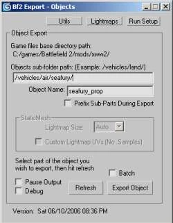
You
can do all this in the original plane scene as we will use 'batch'
export later on to export all of our scene in one flush. You only need
to make sure that the propeller ends up in the Seafury folder to not
scatter parts of the plane across the mod. To accomplish this , select
the root of the propeller and open the BF2 Exporter window. Enter the
path '/vehicles/air/seafury/' into the destination , the subfolder
'seafury_prop' will then be created inside the plane folder.
 |
|---|
Image File: planeAH.jpg
We have both objects (the plane and the propeller) in one scene which is always handy when you want to keep things together, like differnt pieces of bridges, houses with additional ladders or windows or other stuff like helicopters and their rotors. For this reason, the BF2 exporter for Max provides the 'Batch export' feature. If you have prepared the target folders in the root object for your part, the batch export will take care of the target directories and export all your parts in a row. But first lets try out if the export of the propeller part would work. Select the 'root_bundledMesh_seafury_prop' helper and open the BF2 exporter window from the BF2 menu. We already filled in the destination folder and now simply press 'Export Object' If everything is o.k, we get a new folder inside our seafury folder, named 'seafury_prop'. A quick look at the con file should help in finding any
rotations or other anomalies:
GeometryTemplate.create BundledMesh seafury_prop
ObjectTemplate.create Rotor seafury_prop
ObjectTemplate.saveInSeparateFile 1
ObjectTemplate.creator XWW2:mscho
ObjectTemplate.geometry seafury_prop
include seafury_prop.tweak
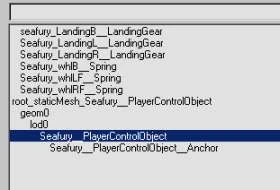
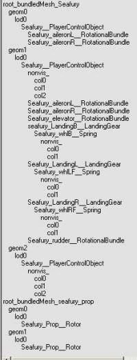
This
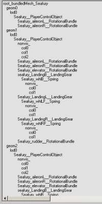
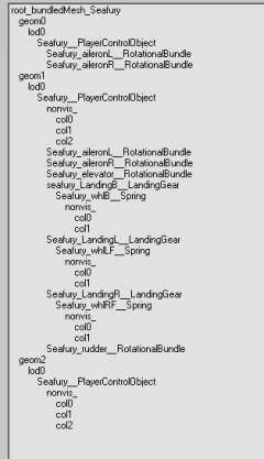
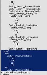
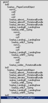
looks good. We now have the rotor object and can forget about it for a while. To recap, our complete model hierarchy now contains the seafurey PCO with all three geoms and the propeller object with 2 geoms:
 |
|---|
Image File: planeAI.jpg
If
you plan to re-export both objects in a row, you only need to check
'batch' in the Exporter window, select the first root object (the plane
in this case) and hit 'Export Object'. Both objects in the scene will
then be exported.
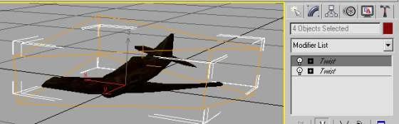
We want a re-export soon as we are going to tamper a bit with the wreck model first. Atm, the wreck looks to good to be believable, lets deform it a bit by adding some bend and twist modifiers on it biggrin.gif Select your wreck main mesh ( geom2 > lod0 > seafury__PlayerControlObject)and its collisionmeshes and hide the rest of the model for now. Select all meshes (PCO and the colmeshes) and add a 'Twist' modifier on top of them. Tamper with its settings until the model looks like being ill-used. You can add another 'Bend' or 'Twist' modifer on top of the stack until you get satisfying results.
 |
|---|
Image File: planeAK.jpg
When
ready, collapse the stack.Our Model is now fully working, but to
improve graphics performance its best to add some lower-poly 'lod'
models of it to the scene. LOD (Level of Detail) models are lower-poly
models shown in the game when you're further away from it. We should add
at least a lod1 to both geom1 (3P model) and the wreck. Don't worry,
this is easily done by again using the 'Clone with childs(Copy)'
function and some tampering with the MultiRes modifier. Lets start with
the wreck. Unhide only the geom2 tree objects, then select the 'lod0'
dummy of the wreck model (geom2) and run the utility then rename the new
dummy to 'lod1'. Lod models don't need collisionmeshes and the
'nonvis_' helper so delete them from the newly created geom2>lod1
tree:
 |
|---|
Image File: planeAJ.jpg
Now
you should hide all objects except the Seafury__PCO in the 'lod1' and
delete details from it which will not be seen from a distance, like
cockpit interior , screws, anything small. When finished, add a
'MultiRes' modifier to it press 'Generate' and reduce vertex count. Keep
in mind this is only seen from far away, so don't hesitate to reduce
polies to a massive amount. The Seafury wreck can be reduced down to 26%
of the original vertex count. When finished, again collapse the
MultiRes modifier.
 |
|---|
Image File: planeAL.jpg
We
will have a lot of dead vertices in the UVmap of this mesh, get rid of
them by adding a 'Unwrap UVW' modifier of this mesh and collapse it. You
can check this by opening 'Channel Info...' from the 'Tools' menu and
checking 'Dead Verts' in the mesh info. We can further improve
performance by adding a lod2 tree to the wreck, do this by 'Clone with
childs(copy)' again on the lod1 , rename the copied lod1 to lod2 and add
another MultiRes modifier on top of the newly created 'Seafury__PCO' in
the lod2 tree. We can reduce another 40% of the vertices and collapse
the modifier on the mesh. We end up with this new wreck hierarchy:
 |
|---|
Image File: planeAM.jpg
For
the main (3P) model we need to think about reducing polies, too but
here we need to keep some of the objects like the landing gears. If we
simply erased them from the lod1 model, the plane would hover above the
ground, looking bad so we need to maintain some of the hierarchy for it.
The sequence of meshes need to be maintained over the different lod
trees. As there is a slight chance that the ailerons will be visible in
the 1P view, we keep them right after the PCO and have to keep them in
the lod1 tree of the 3P view as well as they are followed by the landing
gears in 3P. Lets start by copying the lod0 of the geom1 with children
to a 'lod1'. Erase the collisionmeshes from the newly created lod1 tree
of objects first. As the rudder is the last object in this tree, we can
attach it back to the PCO without disturbing the sequence of meshes.
 |
|---|
Image File: planeAN.jpg
Now
again first go through the lod1 model, erasing everything from it which
won't be seen from a distance. We still have a lot of meshes in the
lod1, it would be tedious work to apply the MultiRes modifier to each of
them seperately. Fortunately, Max allows adding modifiers to multiple
meshes at once. Select all meshes of the lod1 model now and add the
MultiRes modifier to the stack. Looks like we can again tune down
vertices to 26% here. After collapsing the MultiRes modifier, apply an
'Unwrap UVW' modifier and simply collapse it on the objects. (Dead
vertices killed now ). The lod2 model is created accordingly. There we
can delete more meshes, like the landing gear and re-attach control
surfaces, leaving us with only the main PCO:
 |
|---|
Image File: planeAO.jpg
We
now are going to strip down the 1P model where we can save a lot of
polies, too. In the 1P Model, most of the tail is not visible , so we
can get rid of it . The same is true for the underside of the plane and
even faces in front, pointing forward. Select the Seafury__PCO in the
geom0 tree and hide the rest for now. Now delete the complete tail
section and all faces from the underside which will not be visible. On
the other side, we want to have a detailed cockpit, so the cockpit
section will need some refinement. The first thing is the cockpit glass.
Atm the faces of the cockpit glass are only seen from the outside. When
the Player is inside, no faces are visible and we want to change
that.We do that by detaching the cockpit faces and apply a 'Shell'
modifier to it. The shell modifer will duplicate faces, inherit the
uvmap of them and flips normals. The Shell modifier provides a
'thickness' parameter where we can select the thickness of our glass
cockpit. When finished, collapse the modifier and re-attach the cockpit
glass to the hull. Don't forget to collapse an 'Unwrap UVW' modifier on
the model to get rid of dead vertices. Our new 1P model doesn't look too
impressive when seen in 3DS but it does its job quite well:
 |
|---|
Image File: planeAP.jpg
Wow, we should have a complete model now biggrin.gif
. Lets re-export it. To export plane and propeller in a row, select the
root of the first object (which is the plane in our case) and open the
BF2 exporter. Check 'batch' and hit 'Export Object'. Both objects are
now exported and should appear with fresh creation dates in the Seafury
folder.
This post has been edited by mschoeldgen: Sep 19 2009, 07:59 AM
Part 5:
Coding Admittedly, i don't use the editor for all coding but get a basic 'seafury.tweak' file by copying it from another similar object. This will reduce the chance of missing important stuff like armor components , soldier positions and icons. We only need to take care of renaming the object to our new plane , so a good text editor comes in handy here. As we have some working planes in our mod, i start by copying the tweak file from our Hurricane to the Seafury folder and do the same for the seafury_prop.tweak file. Editing the seafury_prop.tweak file is a cinch, just replace the old object name with our new 'seafury_prop' and assign the engine name in it for the
Seafury engine:
rem *** handcrafted by mschoeldgen
GeometryTemplate.compressVertexData 1
GeometryTemplate.maxTextureRepeat 16
ObjectTemplate.activeSafe Rotor seafury_prop
ObjectTemplate.creator XWW2:mscho
ObjectTemplate.modifiedByUser "mscho"
ObjectTemplate.setNetworkableInfo BasicInfo
ObjectTemplate.saveInSeparateFile 1
ObjectTemplate.geometry seafury_prop
ObjectTemplate.floaterMod 0
ObjectTemplate.hasMobilePhysics 0
ObjectTemplate.physicsType Mesh
ObjectTemplate.changeLodAt 0.15
ObjectTemplate.tolerance 9.76565e-005
ObjectTemplate.rotationSpeedMod 2.5
ObjectTemplate.rotationSpeedModBlur 0.1
ObjectTemplate.rotationAxle 2
ObjectTemplate.engineName seafury_motor
'rotationAxle 2' nominates the engine rotation axis, where 0 would be 'Yaw', 1 is 'Pitch' and 2 is 'Roll'. Engines do 'roll', so selecting axis 2 is fine. Save the file as 'seafury_prop.tweak' and close it. Now get the 'seafury.tweak' file and open it. We want to replace all occurences of the old plane name with our new 'seafury' but we need to take care not to change anything which we don't want to, like sound file pathes and icon pathes and names, so a bit of care has to be taken. Also we need to replace the names for ailerons, elevator and rudder to our new objects. As a template we can rely on the .con file, as it carries the names we need. We will have a problem as i can't give away my engine sounds, so we're stuck with either a jeep sound or one of the jet sounds of BF2. For now we code in the jeep_faav sounds which is sufficient for demonstration. Continue to browse through the code and change the objects to the names of our new plane. We will later use the BF2 editor to do a syntax check and position all our editor-added objects to their locations on the Seafury. Editor-added objects are e.g. the damage effects, the sound locations and contrail effects. We will also need to check the loacation of entry points, the camera and other stuff to complete the plane. We also will need 'Wings' which are the non-visible physical parts to give the plane the abilty to fly. Wings are controlled like RotationalBundles , and can carry both a 'WingLift' property which is responsible for the basic airlifting and a 'FlapLift' determining the effectiveness (strength) of the control surface. We will need at least 5 Wings for a basic plane : a 'body' Wing to overcome the basic mass of the plane, 2 aileron Wings to roll the plane , an elevator Wing for pitch and a rudder Wing to yaw the plane. We need to carefully place them as any deviation (especially for the ailerons) lead to unwanted flight characteristics. The best strategy is to place them symmetrical to the length axis of the plane with the same distance to the middle of the plane to the left and the right. Lets fire up the BF2 Editor in Object mode and browse to our Seafury now. When loading the mod, look out for any newly introduced error by our plane - the editor is a good syntax checker. We didn't supply an engine with the model, so this is also to be created in the editor. Select the same name for it you chose in the prop tweak file.
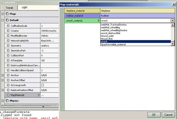
If you haven't done so, launch the editor now in 'Object Editor' mode and browse through the resource window to our new plane. Double-click it to enable editing. The first thing we need to do is to map the plane materials to their BF2 counter parts. You'll find this when selecting the Main model (Seafury) in the resource bar and then look at the 'Default' section in the tweaker window. Find the 'Map materials' entry in the last line:
 |
|---|
Image File: planeBA.jpg
Remember
these names ? Yes, these are the same names we gave the materials in
3DS/gmax, the part before the '||' . Note that only materials for
collisions are shown and mapped here, its not necessary to map any
textures. In this tutorial we cannot go through adding all of the
necessary Wings for the plane, but let me show you how it works for a
single Wing, the rudder. the rudder Wing is a child of the basic body so
we 'Add a new child' to the plane by right-clicking the Seafury PCO and
select 'Add new child'.
Image File: planeBB.jpg
A
list with tons of stuff pops up now, lets select 'Wing' for now. The
editor asks for a name of the new Wing, lets name it
'seafury_rudderWing'. The new Wing is now part of the seafury PCO and
you should find it in the resource list for the plane. Select it by
clicking on it. The initial position for a new object is 0/0/0. the
rudder will be most effective when placed on the tail of the plane, we
should move it there by dragging the marker back to the tail. (If the
3D-marker doesn't show up press show marker in the wizard window). Press
and hold the mouse on the blue arrow and drag it to the rear. Lift it a
bit with the green arrow to place it right on the visible rudder pivot:
 |
|---|
Image File: planeBC.jpg
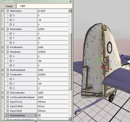
Lets
add some code to it now. Now wings are only able to 'Pitch', so we need
to set the pitch part in the 'Rotation' tweak section of the Wing. (
keep in mind, its Yaw/Pitch/Roll in RotationalBundles and Wings . For a
start, lets code a minimum Rotation of -25 degrees and a maximum of 25.
To make the wing move at all, we need to add a maxSpeed and an
acceleration for it. We also want the user to be able to pitch the wing
with the PIYaw controller, so we map 'InputTo Pitch' to the PIYaw input.
We want the wing to return to the zero position automatically, so lets
check the 'Automatic Reset' box, too. When entered the values, we can
see the marker rotating when tapping the 'A' or the 'D' keys.
 |
|---|
Image File: planeBD.jpg
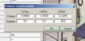
Oh,
great, it's moving, but around the wrong axis ! Wings are limited as
they can only pitch, so we need to rotate the wing around the Roll axis
to 90 degrees.This limitation fortunately doesn't exist for the
RotationalBundles. We rotate the wing this time by numerical entry,
using the 'Show Relative Transform view' feature of the editor.
Right-click the wing in the resource bar and select the relative
transform view. We now have 6 numerical entries available: the position
entries relative to the 0/0/0 point of the PCO and the rotation ,
currently at 0/0/0. Lets enter a rotation of 0/0/-90. We're using -90
degrees here we don't need to invert the controller then. If you ever
have to invert the controller do it by using a negative acceleration on
the Wing or RotationalBundle.
 |
|---|
Image File: planeBE.jpg
After
pressing o.k., the marker has changed orientation and the wing now
reacts as expected. To make it effective , we need to give the wing a
flaplift. You'll find the lift properties in the 'Physics' section of
the tweaker. Initially they are set to 1 for Winglift and 0.1 for
Flaplift, lets change that to 0 for the Winglift and 2.5 for the
Flaplift. A Winglift would be counter-productive for the rudder ,
causing the plane to constantly yaw. If the rudder prooves to be too
weak or too strong, we can tamper with the Flaplift after some flight
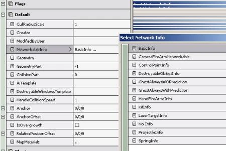
testing. To keep the game happy, we need to finally set the Networkable
Info in the 'Default' tweak for the rudder Wing to 'BasicInfo'. This
should conclude our first Wing. Before we come to the other wings, lets
quickly animate our visible rudder to match the invisible Wing.
 |
|---|
Image File: planeBF.jpg
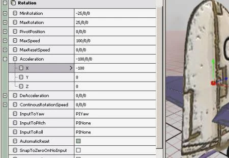
The
visible Rudder is already in the model as we exported it. Now for
RotationalBundles there are no limitations in regard to motion, we can
set minRotation, maxRotation ,Speed and Acceleration in the Rotation
section for 'Yaw' which is the natural movement for the rudder. After
entering the values ( -25,25,100,100 )set the 'InputToYaw' to 'PIYaw'
and check 'Automatic Reset'. It looks not too bad, but the movement is
inverted ! Easy fix, just put in -100 instead of 100 in the
acceleration:
 |
|---|
Image File: planeBG.jpg
We
don't need Networkable Info's for the visible stuff, btw which is great
news as we only have 14 of them for each model. The PCO, Springs,
Engine and movable Wings need them, though. If you have a lot of wheels
in your model, just code four of them to have networkable info,
preferably those which are in the 'corners' of your model. O.k. , our
first wing is ready. Now work your way through the ailerons and the
elevator. You will need to invert one of the aileron wing pitch and do
the same for the visible Rotational bundles, as the ailerons always have
opposing movements, when one aileron goes up, the other goes down. To
have better control over the plane physics, i add a basic 'Body' wing
with only a Winglift. With this Wing i can adjust the basic flying of
the plane and free the Flaps to only take over Flap lift. On full
throttle, a well designed plane should lift off, fly straight and ascend
a little without touching the joystick. This is easily accomplished by
tampering with the winglift of the central body wing.
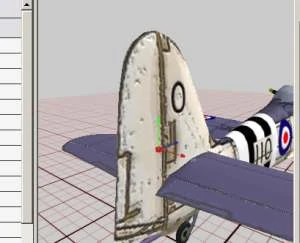
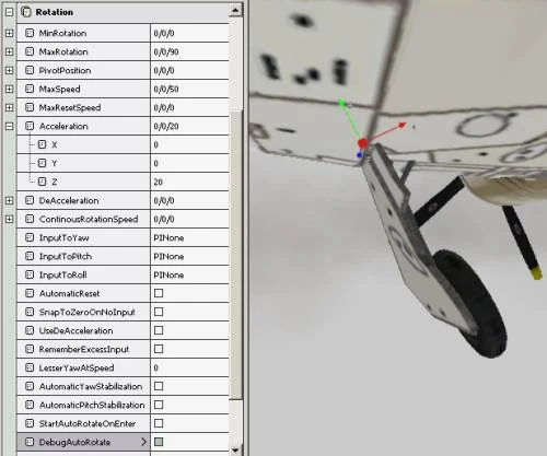
Testing the
Landing Gears is a bit different. Normally they are activated through
the speed and height of the plane and can't be watched very good in the
editor. But the Editor provides the 'DebugAutoRotate' function to
overcome this problem. Select one of the LandingGears and open its
Rotation tweaker. We assume the landing gear will 'roll' from its base
position to completely retracted so we enter some basic values in the
'roll' section. A positive Rotation in BF2 is defined as
counterclockwise. So the left landing gear is currently at its
'minRotation', lets enter 0/0/0 for it. the maxRotation will be close to
90 degrees roll, so we enter 0/0/90 for the maxRotation. Supply values
for speed and acceleration and then, with the free camera, zoom in on
the LG. Now use the 'Input' mode of the camera and check
'DebugAutoRotate' in the tweaker. After a little delay, the Landing Gear
will start to retract until the maxRotation is reached. Unchecking
'DebugAutoRotate' will extend the landing gear again.
 |
|---|
Image File: planeBH.jpg
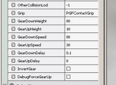
After
you have found good values, remember to uncheck 'DebugAutoRotate'
again. Btw, its possible to rotate a landing gear around more than one
axis at the time, sometimes this comes in handy when having more
complicated retraction sequences. The Seafury, though doesn't have that
fancy stuff. We only notice that one part of the retracted landing gear
sticks out through the wing, but we will have an elegant solution to
this problem soon. Now all we need to do is setting the height and speed
for the landing gear to be activated or deactivated. This is done in
the Physics tweaker with the 'GearDownHeight' and 'GearUpHeight' which
will down/up the gear when a certain height of the PCO is reached and
the 'GearDownSpeed' and GearUpSpeed' doing this dependent on the speed
of the plane.
 |
|---|
Image File: planeBI.jpg
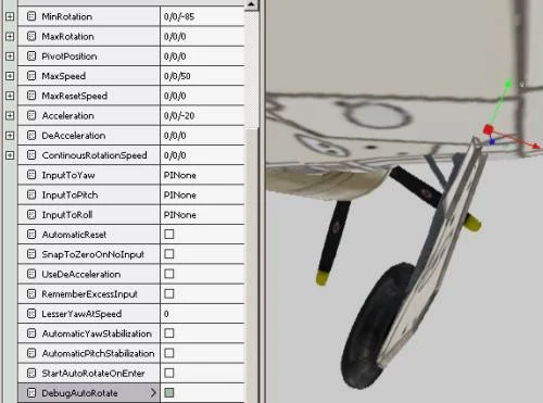
The
right gear is the same thing, but inverted. Her we need to leave the
maxRotation at 0/0/0 and the minRotation will be around 0/0/-90. We now
have a negative rotation , so we will need to set the acceleration to a
negative value:
 |
|---|
Image File: planeBJ.jpg
To
make the plane more complete, we need to add a 'Camera' to it for the
player and an entry point. Simple stuff, just add a new child to the
main PCO , select either 'Camera' or 'Entry Point' and position them
with the markers. Tweaking the Camera position is best done by going to
'Enter' View and then by using 'Show Relative Transform view...'
adjusting the position of it. O.k. there's only the engine left. Add a
new child to the main PCO and select 'Engine', naming it as you did in
the prop tweak: 'seafury_motor'. Assing the 'Plane' type of engine in
the Physics tweaker for it and give it some torque. A value of 1000
seems to be a good start.
ObjectTemplate.create Engine seafury_motor
ObjectTemplate.modifiedByUser "mscho"
ObjectTemplate.setNetworkableInfo BasicInfo
ObjectTemplate.createdInEditor 1
ObjectTemplate.floaterMod 0
ObjectTemplate.hasMobilePhysics 1
rem -------------------------------------
ObjectTemplate.addTemplate S_seafury_motor_RotationRpm
ObjectTemplate.addTemplate S_seafury_motor_Idle
ObjectTemplate.addTemplate S_seafury_motor_Rpm1
ObjectTemplate.setPosition 0/0/-0.011502
ObjectTemplate.addTemplate S_seafury_motor_Rpm2
ObjectTemplate.addTemplate S_seafury_motor_Load
rem -------------------------------------
ObjectTemplate.setMinRotation 0/0/5
ObjectTemplate.setMaxRotation 0/0/3000
ObjectTemplate.setMaxSpeed 0/0/3000
ObjectTemplate.setAcceleration 0/0/500
ObjectTemplate.setDeAcceleration 0/0/800
ObjectTemplate.setInputToRoll PIThrottle
ObjectTemplate.setAutomaticReset 1
ObjectTemplate.setUseDeAcceleration 1
ObjectTemplate.setEngineType c_ETPlane
ObjectTemplate.setTorque 1000
ObjectTemplate.setDifferential 5
ObjectTemplate.setGearUp 0.7
ObjectTemplate.setGearDown 0.3
ObjectTemplate.noPropellerEffectAtSpeed 400
ObjectTemplate.noPropellerEffectAtSpeed 400
ObjectTemplate.defaultAngleOfAttack 25
ObjectTemplate.maxAngleOfAttack 80
ObjectTemplate.attackSpeed 20
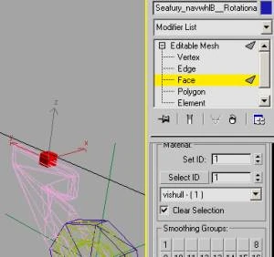
When browsing through the engine code, you'll notice that i have set the minRotation to 5. This has the effect that the prop will start to rotate slowly when the plane is entered and that there's no way to go backwards, just like in real life biggrin.gif ( since BF1942 i have always wondered about backgoing planes , hehehe ) The 'attackSpeed' is sound related. For a dive bomber, you could make use of it to switch on a howling sound when the plane exceeds 'defaultAngleOfAttack' and the attackSpeed. Not yet used here. In the code you'll find an additional MG group with 2 MG's mounted in the wings with alternating fire for demonstration. O.k., looking through the model , there are still 2 things left. The first is the landing gear thing sticking through the wing and the second is maneuvering on the ground. Real planes have the back wheel coupled with the rudder and maybe we should do the same here. It requires us to go back into 3DS , but we can solve both problems with it. We will need a new RotationalBundle between the hull and the rear landing gear first. Create a small box and place it in the desired spot in the rear suspension. Assign your material setup to the box and convert it to editable mesh. Set all faces of it to ID 1 and give it a good name, like 'Seafury_navwhlB__RotationalBundle'. Open the hierarchy Tab for the new mesh and Align the pivot to world, center the pivot to object and Reset Transform and Scale (should be routine for all new objects):
 |
|---|
Image File: planeBK.jpg
Now
make this mesh a child of the main hull in geom1>lod0. Next pick the
'seafury_LandingB__LandingGear' (rear landing gear) and make it a child
of the new RotationalBundle. Introducing this new mesh disturbes our
hierarchy sequence, but we only need to clone the RB and put it into the
lod1 tree to heal as no other lod or geom has the full sequence.
|
|---|
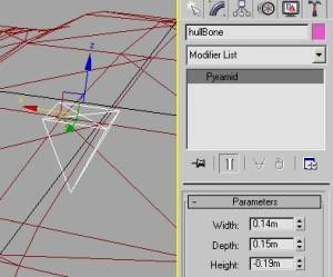
Image File: planeBL.jpg Now we take care of the hydraulic cylinder sticking through the wing. We will do that by using a 'bone' in the main hull and weight the end of the hydraulic stamps to it. This will lead to a deformation of the hydraulic cylinder when the gear is retracted, just what we want. Bones for BF2 purposes are created by 'Pyramid' primitives in Max. Lets first create a pyramid right between the landing gears and make it a child of the main hull. Give it a good name like 'hullBone' and don't convert it to editable mesh ! Size doesn't matter here biggrin.gif you can keep it small and well inside the fuselage. This bone will keep its position all the time and will do the same to any vertex 'weighted' to it.
 |
|---|
Image File: planeBM.jpg
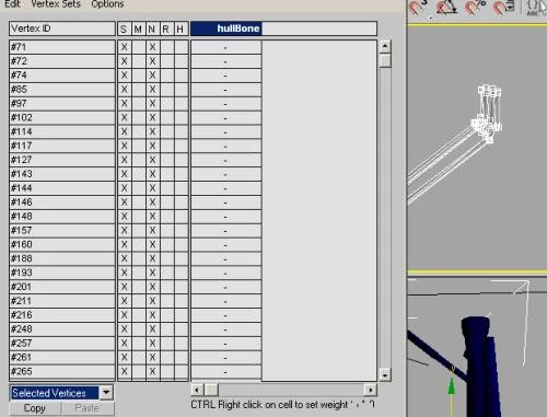
Now
that we have the bone, we have to add 'Skin' modifiers to both landing
gears and weight the affected vertices to the hull bone. Lets go to the
first landing gear and add a 'Skin' modifier. We hide everything except
the landing gears and the bone for now to have a clearer view, 'cause we
have to select the affected vertices in a minute. In the skin modifier
rollout, find 'Parameters' and press 'Add' to select the hullbone.
Scroll further down in the rollout to the 'Advanced Parameters' and set
the 'bone affect limit' to 1, meeting the BF2 requirements. Now scroll
back up and find the 'Edit Envelopes' button. Press it and check
'Vertices' in the Selct all while unchecking 'Envelopes' and 'Cross
sections'. For weighting the vertices , select them, then open the
'Weight Table' further down in the skin rollout. Select 'Selected
Vertices' in the bottom pop-up menu.
 |
|---|
Image File: planeBN.jpg
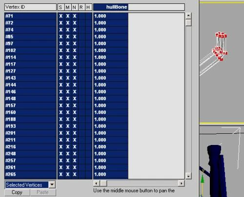
From
the 'Edit' menu , choose 'Select All' . When you now enter a '1' in the
first cell followed by to leave the field, it will be
transferred to all selected vertices and give us the desired weigthing.
At the same time the red color on the vertices in the viewport display
our weighting.
 |
|---|
Image File: planeBO.jpg
Now
do the same for the other landing gear and re-export the model. Time to
launch the editor again. We need to code the new steering and check the
optics of the landing gear. After that we can pack the mod and check
the model ingame. Coding the new RB is like the rudder, give it the same
properties as for the rudder, then the back wheel will be in sync. The
Landing Gear looks good now, too biggrin.gif
. You now need to prepare a map to spawn the new plane and pack the mod
to make the game recognize it. For testing purposes i have a map with
two airfields in it, but you could simply replace a plane on any
existing map within the gameplayobjects.con of the desired gamemode
using a texteditor. O.k. lets launch the game (preferably the debugger)
and lets find bugs . Well, i had a typo in a sound path, but it doesn't
look to bad:
 |
|---|
Image File: planeCA.jpg
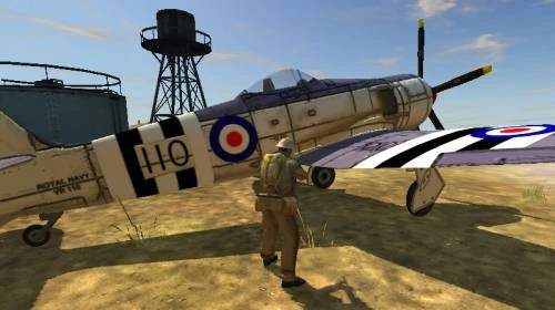
Lets enter it - It flies biggrin.gif
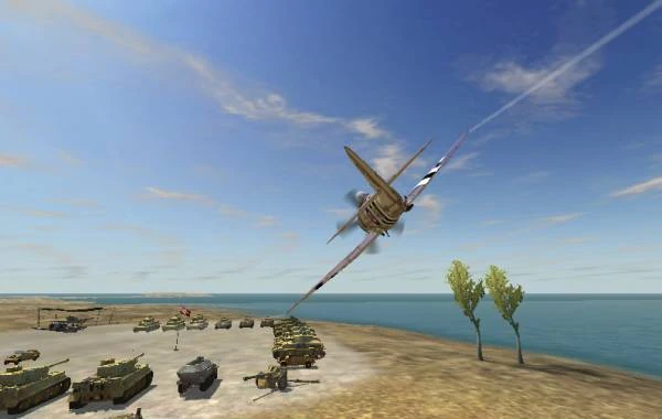 |
|---|
Image File: planeCB.jpg
This
concludes this tutorial. After refining things like the nose camera
position, the back landing gear and the position of the MG group, i will
post the downlink link, containing the Max 7 model, an export to .3DS
for our gmax friends and the complete BF2 vehicle folder to be put into
/vehicles/air/ . To successfully re-export from your machine, you need
to set the texture pathes in your Material Manager as your object isn't
probably located in 'C:\games\Battlefield
2\mods\XWW2\objects\vehicles\air\seafury' where it was on my machine.
Take care to not collapse the Skin modifiers on the Landing Gears, else
you will have to make new ones. Hopefully you could refresh your
knowledge or learn something, for me it was a pleasure to write it.
Sorry 56k users, but a picture says more than a thousand words biggrin.gif
Here now is the download link:
http://www.schoeldgen.de/bf1942/tutorials/Seafury.zip
Known flaws: Sound coding is bad. The Seafury never really had paired MG's , but 4 * 20mm Hispano cannons. Cockpit could need refining, but the model doesn't have production quality anyway.
Historical: The Hawker Seafury was planned in 1943, when the Royal Navy was in need of a new carrier based plane. It is still one of the fastest prop driven planes ever built.