How to Create a single AImesh for Multi-part Objects (WIP)[]
Based on info from Ballard
When creating an AImesh is not uncommon to run into the situation where a multipart object does not navmesh properly and, therefore, creating a single AImesh would be ideal. This is very common with multipart bridges, but is found in other situations, such as some boats.
For this tutorial, we will use two different ships as examples: The cargoship from PR and the us_carrier_wasp from vBF2.
The cargoship has 3 main parts and has no col3s created. The carrier's 4* main parts already each have a col3 created by DICE, so I'm not trying to re-invent the wheel here, it just serves as a good example.
*NOTE - There actually 5 main parts for the carrier, but the col3 of the us_carrier_wasp_interior is a simple pyramid.
The us_carrier_wasp_back section actually has the 'true' col3 mesh of the
'interior' section built into it.
1) Import the collision meshes of the static in Max using the colmeshimp.ms script.
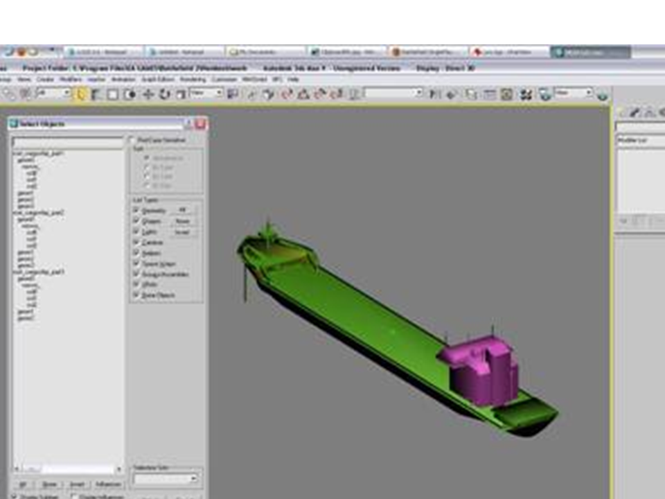
The first example is...PR's 'cargoship'
Here what it looks like after all four parts are imported:
[AImesh1002.jpg]
A couple of important things to note -
- In this case, there is no col3 for any of these parts, so we will have to use the col2 to create our AImesh.
- Fortunately, each part is already perfectly placed so there is no need to preposition any of them. The original creator exported this static with everything placed where it needs to be, not only makes it easier for 'placement' by a mapper, but easier to create the AImesh. Otherwise, We would have to figure out where these pieces 'fit' in relation to each other. Select and delete all the parts that are not needed. We only need the col2s -- soeverything else can go...
[AImesh1004.jpg]
Note: It is easier to work in 'Editable Poly' mode (imported meshes always start out
in 'Editable Mesh' mode).
[AImesh1006.jpg]
and like in the previous tut, I will clear the smoothing groups off and select all the polys and set them to ID1
So I'm going to work starting at 2b and then go through the whole original tutorial until completion. Here was my final nav version of it...
[AImesh1008.jpg]
You can see it is alot simpler than the original parts. I used more detail in the areas I knew would need it for navmeshing purposes and simplified things that were not important.
*********************************************
Now let's do the us_carrier_wasp and note some of the differences... 1) Import the collision meshes of the static in Max using the colmeshimp.ms script.
Here is what it looks like...
[AImesh1010.jpg]
A couple of important things to note -
- Each part has a col3 that we can work off...This is nice
- Unlike PR's 'cargoship', all 4 parts are centered on top of one another, which means this will take some work.
DICE obviously made and exported each part separately without thinking too much on how they should be positioned. So to make a single nav static out of this, we need to figure out a way to position each part so that they are correctly placed. This is where the .con files of these meshes need to be looked at. We are interested in seeing if an 'anchor' was added to their .con files.
Here is the us_carrier_wasp_back.con file...
Code: Select all
GeometryTemplate.create StaticMesh us_carrier_wasp_back CollisionManager.createTemplate us_carrier_wasp_back
ObjectTemplate.create Bundle us_carrier_wasp_back ObjectTemplate.saveInSeparateFile 1 ObjectTemplate.creator GTI-1:gti ObjectTemplate.collisionMesh us_carrier_wasp_back ObjectTemplate.mapMaterial 0 Metal_solid 0 ObjectTemplate.mapMaterial 1 Tarmac 0 ObjectTemplate.hasCollisionPhysics 1 ObjectTemplate.physicsType 3 ObjectTemplate.geometry us_carrier_wasp_back ObjectTemplate.anchor 35.2981/-0.6096/16.3679
include us_carrier_wasp_back.tweak
Sure enough an anchor was added....Here are the other anchors that were added
to the other 3 parts...
Code: Select all
front ObjectTemplate.anchor 211.4774/-0.6096/16.3679 mid ObjectTemplate.anchor 123.3930/-0.6096/16.3679 bridge ObjectTemplate.anchor 123.3930/-25.4583/16.3679
So the next question is what do you do with this info? We'll get to that, but let's take care of other things first. Like with the 'cargoship', select and delete all the parts that are not needed. We only need the col3s, so everything else can go...
[AImesh1012.jpg]
I also will work in 'Editable Poly' mode, clear the smoothing groups, and set all polys to ID1
Now, about getting these parts into their correct positions... You need to select one of the parts as your 'base'....The 'base' is what the other 4 parts will be positioned off of.
The rear seems like the best candidate for the 'base' (I imagine any of the parts would work, but working rear to front seems best in this case)
I will also move the parts just so they aren't all bunched up on another...putting them in relatively correct positions...
[AImesh1014.jpg]
IMPORTANT NOTE - The Editor and Max do not view the axis' in the same fashion. The Editor views 35.2981/-0.6096/16.3679 as...
Code: Select all
X axis = 35.2981 Y axis = -0.6096 Z axis = 16.3679
3ds max views 35.2981/-0.6096/16.3679 as...
Code: Select all
X axis = 35.2981 Y axis = 16.3679 Z axis = -0.6096
The Y axis in the Editor controls height, in Max the Z axis controls it
The Z axis in the Editor controls right to left movement, in Max the Y axis
controls it
So be aware of this!
Plug the Y axis info you have into the Z axis in Max
Plug the Z axis info you have into the Y axis in Max
Another IMPORTANT NOTE - I use a scale of 10 when working in Max. Meaning a value of 10.0 = 1 meter on the meshes So a number like 35.2981 in game needs to be translated to 352.981 in Max
Your settings could be different and there is no right or wrong way, but JUST BE AWARE!!!
-----------------------------------------------
Let's first set the position of the 'mid' section... We use the anchor info of the back (since it's our 'base' 35.2981/-0.6096/16.3679) and subtract it from the anchor info of the mid (123.3930/-0.6096/16.3679)
Code: Select all
X axis - 35.2981 - 123.3930 = -88.0949
Since the values for the other 2 axis' are the same, they will = 0
Code: Select all
Y axis - 16.3679 - 16.3679 = 0
Code: Select all
Z axis - -0.6096 - -0.6096 = 0
Remember that I'm on a scale of 10, so -88.0949 becomes -880.949
So I select the 'mid' section and enter this value into Max.
Looks pretty good...
[AImesh1016.jpg]
Let's set the position of the 'front' section... We use the anchor info of the back (since it's our 'base' 35.2981/-0.6096/16.3679) and subtract it from the anchor info of the front (211.4774/-0.6096/16.3679)
Code: Select all
X axis - 35.2981 - 211.4774 = -176.1793
Since the values for the other 2 axis' are the same, they will = 0
Code: Select all
Y axis - 16.3679 - 16.3679 = 0
Code: Select all
Z axis - -0.6096 - -0.6096 = 0
Again, I'm on a scale of 10, so I select the 'front' section and enter
-1761.793
[AImesh1018.jpg]
You can't see it in the screenshot, but there is some clipping that is occurring.
Looking at it a little closer it seems to be where it needs to be, plus the info I'm using isn't lying, so I can only trust what I'm given!
Finally, let's set the position of the 'bridge'... We use the anchor info of the back (since it's our 'base' 35.2981/-0.6096/16.3679) and subtract it from the anchor info of the bridge (123.3930/-25.4583/16.3679)
Code: Select all
X axis - 35.2981 - 123.3930 = -88.0949
Code: Select all
Y axis - 16.3679 - 16.3679 = 0
Code: Select all
Z axis - -0.6096 - -25.4583 = 24.8487
Scale of 10, so the X axis becomes -880.949
We now have the Z axis to factor in...
Scale of 10, so the X axis becomes 248.487
[AImesh1020.jpg]